The Back End

Return to Atmos Spec or Back to main page
What, no joystick ports? What has the Oric got round the back ? Not too much really. When the Oric was designed joysticks weren't used a great deal, so there are no joystick ports. Joysticks were a later addition from Oric and third party companies. Some worked via the expansion port but most worked via connection to the printer port. This worked well but sound was effected, because the 6522 is used by both the sound chip and the printer port.
Really the Oric doesn't need a joystick as the cursor/ space-bar on the bottom row of the keyboard is so good for playing games. Some programmers seemed blind to the layout and used old key layouts using Z,X, ',/ which I find odd on an Oric.
Where's the RS232 ? You also won't find a (serial) RS232 port on the Oric. Oric recognised the need for a decent printer port and used the (parallel) Centronics port. This means that the Oric could be used with virtually any printer at the time. Nowadays it is hard to tell what injet printers will work. The early Cannon BJ models did work because they featured Epson emulation.
An RS232 is needed to connect things like a modem. Those of you that have a modem will have an RS232. This is the small black box that fits into the expansion BUS. You can use this with the Modem removed for other things that mat require a serial interface.
What has it got then ? OK, from the left you have the TV connection designed for UK PAL systems and set to channel 36. If you don't have a lead make up one using a phono plug for the Oric and a coaxial cable or similarly screened cable connected to a standard TV/ coax plug at the other end.
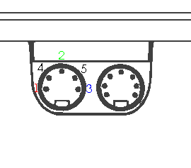
Next is the RGB monitor connection. Different monitors have different sockets so I can't tell you how to connect at that end. You can use this socket to connect to a SCART, RGB or a composite video connection. Use screened cable !
 |
The Oric manual numbers the
pins in this way.
|
So how do you connect the Oric RGB port to a
SCART/ Peritel/ Euroconnector ?
I had a diagram but it may only work with some TVs - for a better
diagram try the one on Dbug's site.
http://www.defence-force.org/computing/oric/hardware/video/index.htm
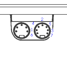
Cassette & Sound The next DIN plug to the left of the RGB is the cassette port. There are various types of lead that have been used but the best is one with 3 jack plugs. One small (2.5mm) one turns the cassette motor on adn off which makes for easier loading. The other two 3.5mm jacks are for ear and mic.
N.B. Also in this socket are connections for sound. You can make a lead to plug into your hifi for great sound ! If you want to use the this and cassettes you'll need a DIN plug with two cables coming out of it.
 |
1. Tape Out 2. Ground 3. Tape In 4. Sound 5. Sound 6. Relay Contact (cassette motor control) 7. Relay Contact |
As far as I remember it doesn't matter which way round the connections are for the two sound, or the two Relay connections.
Centronics Printer Port This is not the standard printer port we know today, but a 20 pin IDC plug. A great improvement on the awful edge connectors which relied on sockets being shoved onto the circuit board. You can't buy printer leads ready made up. You need to have one made - or make one your self.
|
These are the port connections.8 data lines, strobe
and Ack. To connect a Centronics plug attach a 20 pin
plug to one end of some 20 way IDC cable. (At least a metre.) The cable goes to one side of the Centronics plug - from pin number 1. |
BUS Expansion. Most
people now use this to connect their disk interface so it is in
use all the time. This is a good reason for using a joystick that
will connect to the printer port. The Cumana interface did have a
place for an expansion port adn I assume devices were intended to
be added here so that you could use them and the disk system
together. AS far as I know this has never been done and the
connector is usually left off the board.
Anyone wanting to dable with interfaces and additions, (such as
the colour expansion board features in Micr'Oric), to the Oric
will need to know these pin connections so, here they are.
| MAP | 1 | 2 | ROMDIS |
| 02 | 3 | 4 | RESET |
| I/O | 5 | 6 | I/O Control |
| R/W | 7 | 8 | IRQ |
| D2 | 9 | 10 | D0 |
| A3 | 11 | 12 | D1 |
| A0 | 13 | 14 | D6 |
| A1 | 15 | 16 | D3 |
| A2 | 17 | 18 | D4 |
| D5 | 19 | 20 | A4 |
| A5 | 21 | 22 | D7 |
| A6 | 23 | 24 | A15 |
| A7 | 25 | 26 | A14 |
| A8 | 27 | 28 | A13 |
| A9 | 29 | 30 | A12 |
| A10 | 31 | 32 | A11 |
| +5V | 33 | 34 | GND |
Power. The last little hole on the Oric is where you connect your power supply. This is a 9V DC supply (center positive)and the original is 5.4 VA. Supplies of 1A seem to work and you can use the original Specturm power supply with the polarity reversed. NB do NOT use the 128K Spectrum power supply which is different !!!
© Copyright 2000 by S.D. Marshallemail me